Схемы > Аудио > 300Вт УМЗЧ для сабвуфера
300Вт УМЗЧ для сабвуфераRod Elliott (ESP)
Introduction
High power amps are not too common as projects,
since they are by their nature normally difficult to build, and are expensive.
A small error during assembly means that you start again - this can get very
costly. I recommend that you use the PCB for this amplifier, as it will save
you much grief. This is not an amp for beginners working with Veroboard!
The amplifier can be assembled by a reasonably
experienced hobbyist in about three hours. The metalwork will take somewhat
longer, and this is especially true for the high continuous power variant. Even
so, it is simple to build, compact, relatively inexpensive, and provides a level
of performance that will satisfy most requirements.
WARNINGS:
- This amplifier is not trivial, despite its
small size and apparent simplicity. The total DC is over 110V, and can kill
you.
- The power dissipated is such that great care
is needed with transistor mounting.
- The S300 is intended for intermittent duty
on 4 Ohm loads, as will normally be found in a subwoofer. It is NOT intended
for PA or any other continuous duty, and although it may work fine for may
years, I absolutely do not recommend this.
- For continuous duty, do not use less than 8
Ohms.
- There is NO
SHORT CIRCUIT PROTECTION. The amp is designed to be
used within a subwoofer enclosure, so this has not been included. A short on
the output will almost certainly destroy the amplifier.
DO NOT ATTEMPT THIS AMPLIFIER AS YOUR FIRST
PROJECT
Description
Please note that this amp is
NOT designed for continuous high power
into 4 Ohms. It is designed for intermittent duty, suitable for an equalised
subwoofer system (for example using the ELF principle - see the Project Page for
the info on this circuit). Where continuous high power is required, another 4
output transistors are needed, wired in the same way as Q9, Q10, Q11 and Q12,
and using 0.1 ohm emitter resistors.
Continuous power into 8 ohms is typically over
150W, and it can be used in the form shown at full power into an 8 ohm load all
day, every day. The additional transistors are only needed if you want to do
the same thing into 4 ohms!
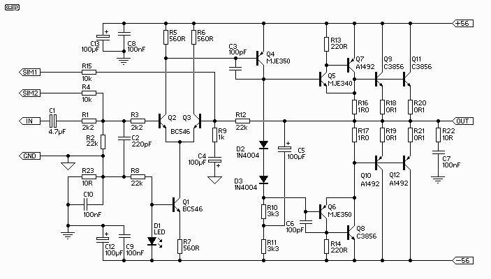
The circuit is shown in Figure
1, and it is a reasonably conventional design. Connections are provided for the
Internal SIM (published elsewhere on the Project Pages), and filtering is
provided for RF protection (R1, C2). The input is via a 4.7uF bipolar cap, as
this provides lots of capacitance in a small size. Because of the impedance,
little or no degradation of sound will be apparent. A polyester cap may be used
if you prefer - 1uF with the nominal 22k input impedance will give a -3dB
frequency of 7.2Hz, which is quite low enough for any sub.

Figure 1 - Basic Amplifier Schematic
The input stage is a conventional long-tailed
pair, and uses a current sink (Q1) in the emitter circuit. I elected to use a
current sink here to ensure that the amp would stabilise quickly upon
application (and removal) of power, to eliminate the dreaded turn on "thump".
The amp is actually at reasonably stable operating conditions with as little as
+/-5 volts! Note also that there are connections for the SIM (Sound Impairment
Monitor), which will indicate clipping better than any conventional clipping
indicator circuit. See the Project Pages for details on making a SIM circuit.
The Class-A driver is again conventional, and
uses a Miller stabilisation cap. This component should be either a 500V ceramic
or a polystyrene device for best linearity. The collector load uses the
bootstrap principle rather than an active current sink, as this is cheaper and
very reliable (besides, I like the bootstrap principle :-)
| |
All three driver transistors must be on a
heatsink, and D2 and D3 should be in good thermal contact with the driver
heatsink. Neglect to do this and the result will be thermal runaway, and
the amp will fail. |
It is in the output stage that the power
capability of this amp is revealed. The main output is similar to many of my
other designs, but with a higher value than normal for the "emitter" resistors
(R16, R17). The voltage across these resistors is then used to provide base
current for the main output devices, which operate in full Class-B. In some
respects, this is a "poor-man's" version of the famous Quad "current dumping"
circuit, but without the refinements.
Although I have shown 2SC3856 and 2SA1492
output transistors, most constructors will find that these are not as easy to
get as they should be. The alternatives are MJL21193 / MJL21194 or 2SC3281 /
2SA1302 respectively.
Use a standard green LED (do not use high
brightness or other colours) - this may be a miniature type if desired. The
resistors are all 1/4W (preferably metal film), except for R10, R11 and R22,
which are 1W carbon film types. All low value resistors (1 ohm and 0.1 ohm) are
5W wirewound types.
Because this amp operates in "pure" Class-B
(something of a contradiction of terms, I think), the high frequency distortion
will be relatively high, and is unsuited to high power hi-fi. At the low
frequency end of the spectrum, there is lots of negative feedback, and
distortion is actually rather good, at about 0.04% up to 1kHz.
Power output into 4 ohms is over 250W
continuous, and for transients exceeds 300W easily. Use of a big power
transformer and massive filter caps will allow the amp to deliver close to 350W
continuous, but if you really want to use it like that, I very strongly
recommend the additional output transistors (see above comments on this topic).
Power Dissipation Considerations
I have made a lot of noise about not using this amp for continuous duty into 4
ohms without the extra transistors. A quick calculation reveals that at the
worst case, the output and transistor voltage will be the same - i.e. at 28V.
With 28V, load (and transistor) current is 7A, so the instantaneous dissipation
is therefore 28 * 7 = 196W. This means that the four final transistors do most
of the work, with the others having a relatively restful time.
Since I like to be conservative, I will assume
that they contribute no more than about 1.5A (which is about right). This means
that they only dissipate 48W, with the main O/P devices dissipating a peak of
74W each. The specified transistors are 130W, and the alternatives are 150W, so
where is the problem?
The problem is simple - the
rated dissipation for a transistor is with a case temperature of 25oC.
As the amp is used, the case gets hot, and the standard derating curves should
be applied. Add to this the reactive component as the loudspeaker drives
current back into the amp, and it becomes all to easy to exceed the device
dissipation limits.

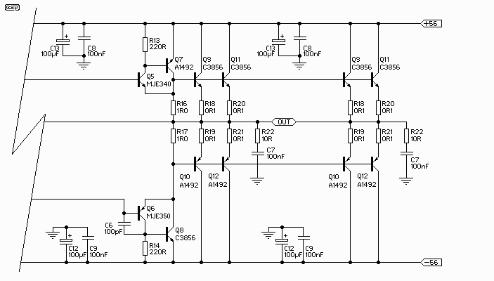
Figure 1a - Double Output Stage
Figure 1A shows the doubled output stage, with
Q9, Q10, Q11 and Q12 simply repeated - along with the emitter resistors. Each
1/2 stage has its own zobel network and bypass caps as shown, as this is the
arrangement if the dual PCB version is built. When you have this many power
transistors, the amp will happily drive a 4 ohm load all day - with a big enough
heatsink, and / or forced cooling (highly recommended, by the way).
A Few Specs and Measurements
The following figures are all relative to an output power of 225W into 4 ohms,
or 30V RMS at 1kHz, unless otherwise stated. Noise and distortion figures are
unweighted, and are measured at full bandwidth. Measurements were taken using a
300VA transformer, with 6,800uF filter caps.
Mains voltage was about 4% low when I did the
tests, so power output will normally be slightly higher than shown here if the
mains are at the correct nominal voltage.
| Gain |
27dB |
| Power (Continuous) |
240W (4 ohms) |
| |
153W (8 ohms) |
| Peak Power - 5 ms |
185W (8 ohms) |
| Peak Power - 10 ms........ |
172W (8 ohms) |
| Input Voltage |
1.3V |
| Noise |
-63dBV (ref. 1V) |
| S/N Ratio |
92dB |
| Distortion |
0.4% |
| Distortion (@ 4W) |
0.04% (1 Khz) |
| Distortion (@ 4W) |
0.07% (10 kHz) |
| Slew Rate |
> 3V/us |
| Power Bandwidth |
30 kHz |
These figures are quite respectable, especially
considering the design intent for this amp. While it would not be really
suitable for normal hi-fi, even there it is doubtful that any deficiencies would
be readily apparent, except perhaps at frequencies above 10kHz. While the amp
is certainly fast enough (and yes, 3V/us actually is fast enough - full power is
available up to 30kHz), the distortion will be a bit too high.
Note that the "peak power" ratings represent
the maximum power before the filter caps discharge and the supply voltage
collapses. I measured these at 5 milliseconds and 10 milliseconds. Performance
into 4 ohm loads will not be quite as good, as the caps will discharge faster.
The supply voltage with zero power measured exactly 56V, and collapsed to 50.7V
at full power into 8 ohms, and 47.5V at full power into 4 ohms.
Power Supply
|
WARNING: Mains wiring must be performed by a qualified electrician - Do not
attempt the power supply unless suitably qualified. Faulty or incorrect
mains wiring may result in death or serious injury. |
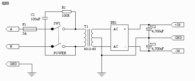
The basic power supply is shown
in Figure 2. It is completely conventional in all respects. Use a 40-0-40 V
transformer, rated at 300VA for normal use. For maximum continuous power, a
500VA or bigger transformer will be needed. This will give a continuous power
of about 350W, and peak power of close to 400W is possible with a good
transformer. Remember my warnings about using the amp in this way, and the need
for the additional output transistors.

Figure 2 - Basic Power Supply Circuit
For 115V countries, the fuse should be 6A, and
in all cases a slow blow fuse is required because of the inrush current of the
transformer.
C1 must be rated for 240V AC (or 120V AC)
operation - do not use standard 250V DC caps under any circumstance, as they
will fail, and R1 will explode! This is not intended as humour - this is fact!
C1 and R1 may be omitted in most cases, and if you cannot get a mains rated
capacitor I suggest that you don't install these components.
The supply voltage can be expected to be higher
than that quoted at no load, and less at full load. This is entirely normal, and
is due to the regulation of the transformer. In some cases, it will not be
possible to obtain the rated power if the transformer is not adequately rated.
Bridge rectifiers should be 35A types, and
filter capacitors must be rated at a minimum of 63V. Wiring needs to be heavy
gauge, and the DC must be taken from the capacitors - not from the bridge
rectifier.
Although shown with 4,700uF filter capacitors,
larger ones may be used. Anything beyond 10,000uF is too expensive, and will
not improve performance to any worthwhile degree. Probably the best is to use
two 4,700uF caps per side (four in all). This will actually work better than a
single 10,000uF device, and will be cheaper as well.
NOTE: It
is essential that fuses are used for the power supply. While they will not stop
the amp from failing (no fuse ever does), they will prevent catastrophic damage
that would result from not protecting the circuit from over-current conditions.
Fuses can be mounted in fuseholders or can be inline types. The latter are
preferred, as the supply leads can be kept as short as possible. Access from
outside the chassis is not needed - if the fuses blow, the amplifier is almost
certainly damaged.
What Does It Look Like?
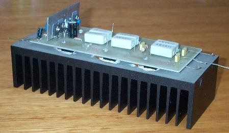
I have included a photo of the
prototype amp, fully mounted on its heatsink. For normal use, some brackets
would also be needed to mount the heatsink, unless two assemblies were used as
the side panels of a conventional (stereo) amplifier chassis.

Figure 3 - Completed Amp Module
As can be seen, this is the single board
version. The driver transistors are in a row, so that a single sheet aluminium
heatsink can be used for all three. Holes are provided on the board so the
driver heatsink can be mounted firmly, to prevent the transistor leads breaking
due to vibration. This is especially important if the amp is used for a powered
subwoofer, but will probably not be needed for a chassis mounted system.
The driver and main heatsinks shown are
adequate for up to 200W into 4 ohms with normal program material. The bits of
wire you can see were used for hooking the amp up to a test supply for the
measurements and listening tests. The power transistors are all mounted
underneath the board, and the mounting screw heads can be seen on the top of the
board.
Deceptively simple, isn't it?
Дата публикации: 2004-02-26
Прочтено: 35004
Версия для печати:  | 
 Главная
 Схемы
Схемы
 Студентам
 Программы
 Поиск
Поиск
 Top50
Top50

 Главная
 Схемы
Схемы
 Студентам
 Программы
 Поиск
Поиск
 Top50
Top50